Zombie Rock Music to Get You Through the Apocalypse
Looking for some Zombie Rock Music to help get you through the Apocalypse? Check out our top 10 picks…


Looking for some Zombie Rock Music to help get you through the Apocalypse? Check out our top 10 picks…
A blog about the epicness that is Zelda rock music. How rock music and Zelda go together Many people…
Zimbabwe’s rock music scene is on the rise, with new bands and artists emerging and making a name for…
Who knew that zen rock music could have such a calming effect? We certainly didn’t, but we’re glad we…
If you’re looking for a fun workout, look no further than a Zumba class to the beat of rock…

You Rock My World – Sheet Music for Your Next Performance. You can find the sheet music for your…
Yurt Rock Music is the new sound of the scene. This type of music is influenced by the sound…

A guide to the best young rock musicians out there today. If you’re looking for fresh new talent in…
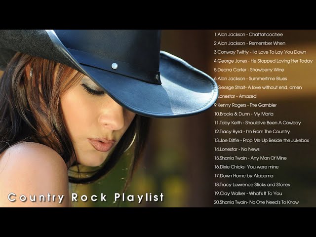
Looking for some new country rock music to add to your You Tube playlist? Check out our recommendations for…
You Rock My World: The Music Video is a must-have for any music fan. Featuring the late Michael Jackson…

You Only Rock Once is a music blog that chronicles my life in music. I’ll be sharing stories, insights,…
You Rock Music is the best place to find new music. With our massive collection of songs, you’re sure…